Heat input effect on the microstructural transformation and mechanical properties in GTAW welds of a 409L ferritic stainless steel
Jorge A. Delgadoa, Ricardo R. Ambriza*, Ricardo Cuenca-Álvareza, Norma Alatorrea, Francisco F. Curielb
aInstituto Politécnico Nacional CIITEC-IPN, Cerrada de Cecati S/N, Col. Sta. Catarina C.P 02250 Azcapotzalco, DF, México
bUniversidad Autónoma de Coahuila (UAdeC), Facultad de Metalurgia, Carr. 57, Km 5, Monclova, Coahuila, México
*Corresponding author: rrambriz@ipn.mx
| |
ABSTRACT
Welds without filler metal and welds using a conventional austenitic stainless steel filler metal (ER308L) were performed
to join a ferritic stainless steel with Gas Tungsten Arc Welding process (GTAW). Welding parameters were adjusted to obtain
three different heat input values. Microstructure reveals the presence of coarse ferritic matrix and martensite laths in the
Heat Affected Zone (HAZ). Dilution between filler and base metal was correlated with the presence of austenite, martensite
and ferrite in the weld metal. Weld thermal cycles were measured to correlate the microstructural transformation in the HAZ.
Microhardness measurements (maps and profiles) allow to identify the different zones of the welded joints (weld metal, HAZ,
and base metal). Comparing the base metal with the weld metal and the HAZ, a hardness increment (~172 HV0.5 to ~350 HV0.5 and ~310 HV0.5, respectively) was observed, which has been attributed to the martensite formation. Tensile strength of the welded joints
without filler metal increased moderately with respect to base metal. In contrast, ductility was approximately 25% higher
than base metal, which provided a toughness improvement of the welded joints.
|
| |
RESUMEN
Efecto del calor de aporte sobre la transformación microestructural y las propiedades mecánicas en soldadura GTAW de un acero
inoxidable ferrítico 409L. Se llevaron a cabo soldaduras sin material de aporte y empleando un electrodo convencional (ER308L) para unir un acero inoxidable
ferrítico, empleando el proceso de soldadura de arco con electrodo de tungsteno (GTAW). Los parámetros de soldadura fueron
ajustados para obtener tres valores diferentes de calor de aporte. La microestructura revela la presencia de una matriz ferrítica
gruesa y placas de martensita en la Zona Afectada por el Calor (ZAC). La dilución entre el metal base y de aporte fue correlacionada
con la presencia de austenita, martensita y ferrita en el metal de soldadura. Los ciclos térmicos de la soldadura fueron medidos
para correlacionar la transformación microestrutural en la ZAC. Mediciones de microdureza (mapas y perfiles), permitieron
identificar las diferentes zonas de las uniones soldadas (metal base, ZAC y metal de soldadura). Se observó un incremento
de dureza en el metal de soldadura (~350 HV0,5) y en la ZAC (~310 HV0,5), en relación al metal base (~172 HV0,5), que se ha atribuido a la formación de martensita. La resistencia a la tensión de las uniones soldadas sin metal de aporte
aumentó ligeramente con respecto al metal base. En cambio, la ductilidad se incrementó aproximadamente un 25% en relación
al material base, lo cual mejoró la tenacidad de las uniones.
|
1. INTRODUCTIONTOP
Ferritic Stainless Steels (FSS) with low chromium (11-12 wt%) and carbon below of 0.03 wt%, present a ferritic matrix at
room temperature. These materials show a high performance in aqueous environments, and frequently are used to replace carbon
and galvanized steels in mildly corrosive environments (Sathiya et al., 2007; Shanmugam et al., 2009). These steels are used extensively in transport industry, the main application is the fabrication of structures in passenger
vehicles, trucks and wagons (Bayraktar et al., 2006; Mukherjee and Pal, 2012). Nevertheless, after a welding process, these materials suffer alterations due to the weld thermal cycles, i.e. microstructural
transformation from austenite to martensite in the Heat Affected Zone (HAZ). Additionally, grain growth in the HAZ can occur
due to high temperatures during welding (Katundi et al., 2010). These aspects tend to modify the mechanical properties and corrosion resistance of the welded joints (Okada et al., 1999; Bayraktar et al., 2011; Niekerk and Toit, 2011; Lakshminarayanan and Balasubramanian, 2012).
On the other hand, when the temperature increases, FSS can transform to austenite or austenite plus ferrite according to the
equilibrium Fe-Cr phase diagram. During welding, the isothermal sections close to the fusion zone can be higher than 1000
°C. This aspect produced a non-equilibrium microstructural transformation from austenite to martensite in the HAZ, due to
the fast cooling rate. In this context, Hakeem and Shahjahan (2009) studied the microstructural characteristics produced under different heat input rates. They reported that irrespective of
the welding condition, the primary solidification structure changes from a predominantly ferritic structure to inter-dendritic
martensite matrix in the weld metal. Pekkarinen and Kujanpää (2010), determined empirically the microstructural changes in FSS controlling the heat input parameters in laser welds. They concluded
that the microstructure in weld metal is fully martensitic, independently of the welding parameters used. Lakshminarayanan
et al. (2009) investigated the effect of different welding processes such as Shielded Metal Arc Welding (SMAW), Gas Metal Arc Welding
(GMAW) and Gas Tungsten Arc Welding (GTAW) on tensile and impact properties of AISI 409M FSS on butt welded joints of 4 mm
in thickness. They found that GTAW joints have superior tensile and impact properties compared with SMAW and GMAW welded joints.
This aspect was mainly due to the presence of finer grains in the weld metal and HAZ.
This paper is focused on describe the behavior of the heat input and dilution percent effect on the microstructure, tensile
properties and indentation of a 409L stainless steel with rectangular shapes welded by GTAW. These welded joints are mainly
used in the construction of structures for passenger buses.
2. MATERIALS AND METHODSTOP
Rectangular shape profiles of a 409L stainless steel (0.029 C, 11.63 Cr, 0.486 Ni, 0.237 Si, 1.86 Mn weight %) of 1.65 mm
in thickness and commercial 308L (0.015 C, 19.63 Cr, 10.26 Ni, 0.68 Si, 1.68 Mn mass %) filler metal were used.
Metallographic samples were prepared in the longitudinal (L), long transverse (LT) and short transverse (ST) directions (Fig. 1a) by using conventional techniques of cutting, machining, grinding and mirror polish. To reveal the microstructure of the
base metal and welded joints, an etching reagent of 50 ml HNO3, 50 HCl and 50 ml H2O was used. The samples were immersed for 30 seconds. Quantitative optical metallography was performed to determine the number
of grains, diameter and grain size areas for L, LT, and ST plane directions.
|
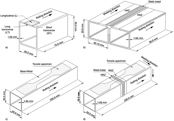 Figure 1. a) Schematic representation for the metallographic samples taken for L, ST, and LT directions, b) edge joint with filler metal,
c) and d) localization for tensile samples of base metal and butt joint (respectively) welded with and without filler metal. Figure 1. a) Schematic representation for the metallographic samples taken for L, ST, and LT directions, b) edge joint with filler metal,
c) and d) localization for tensile samples of base metal and butt joint (respectively) welded with and without filler metal.
|
|
GTAW process was used to join the 409L stainless steel employing direct current electrode negative (DCEN), voltage of V = 14 V, current of I = 120 A. Argon gas shielding gas was used with a flow rate of 1.55 m3 hr−1. The welding displacement v, and wire feeding rate w, were established to obtain three different heat inputs q (Table 1) according to the joint configurations shown in Fig. 1(c and d).
Table 1. Welding parameters
| Specimen configuration |
V (V)
|
I (A)
|
v (mm s−1)
|
w (mm s−1)
|
q (J mm−1)a |
| Edge joint with filler metal (SS-E) |
14 |
120 |
1.23 |
2.87 |
820 |
| Butt joint with filler metal (SS-B1) |
14 |
120 |
1.43 |
2.58 |
705 |
| Butt joint without filler metal (SS-B2) |
14 |
120 |
1.72 |
N/A |
586 |
a,  , where η is the thermal efficiency for GTAW taken at 0.6 , where η is the thermal efficiency for GTAW taken at 0.6
|
To determine the weld thermal cycles within the HAZ, K-type thermocouples were placed on the butt joint welded with filler
metal (SS-B1). For the data acquisition, an analogic-digital conversion system by using a NI9213 card was used. The signal
was digitalized in LabVIEW software® at 100 Hz for each thermocouple.
After welding, cross sectional samples were cut and prepared to determine the percent of dilution (% Dilution). From the geometrical characteristics of the welding profiles the percent of dilution was calculated applying Eq. (1), (Mukherjee
and Pal, 2012). The welding areas where obtained for the edge and butt joints as shown in Fig. 2 (b, c and d).

|
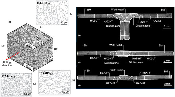 Figure 2. a) Granular structure for the 409L ferritic stainless steel for L, LT and ST plane directions and its respective grain boundary
representation, b), c) and d) different zones of the welding profiles. Figure 2. a) Granular structure for the 409L ferritic stainless steel for L, LT and ST plane directions and its respective grain boundary
representation, b), c) and d) different zones of the welding profiles.
|
|
The mechanical behavior was evaluated by means of tensile tests and indentation measurements (micro and nanoindentation).
The tensile behavior of the base metal and welded joints (Fig. 1 c-d) was obtained by using a hydraulic machine with a load capacity of 100 kN at constant cross head speed displacement of
1 mm min−1. The increase in length of the reduced section for each sample was measured by an extensometer with a 50 mm gage in length,
following the ASTM E8 (2004).
For the microhardness measurements, a load of 0.5 kg (4.905 N) was applied by using a Vickers indenter during a dwell-time
of 15 seconds following a virtual mesh. Mean results at equivalent positions were plotted as microhardness profiles along
the perpendicular distance of the welding profile. Also a microhardness mapping representation was obtained.
Instrumented indentation measurements on different zones of the welded joints were performed with a CSM indentation tester,
equipped with a Berkovich indenter. The maximum indentation load was 500 mN and dwell-time of 15 seconds. A constant time
of 60 seconds for each indentation was fixed without considering the dwell-time applied at the maximum indentation load. From
instrumented indentation an approximation of the elastic modulus for base metal, weld metal and HAZ was obtained. Additionally,
the hardness for the different phases was measured and compared with that obtained for classical Vickers microhardness.
3. RESULTS AND DISCUSSIONTOP
3.1. Base metal microstructureTOP
Figure 2a shows the microstructure of the 409L stainless steel for L, LT, and ST directions. As observed in Fig. 2a, the L and ST plane directions show elongated grains with an equiaxed morphology. The average diameter was similar in both
directions, however, an important difference for LT direction was observed. The highest average density of area corresponds
to L plane, followed by ST plane, and finally LT plane. From Fig. 2a, it is possible to note that the average density of area has a direct influence on the hardness of the material for each
direction, i.e. finer grain size promotes an increment in hardness.
3.2. Macro and microstructural characteristics of the welded jointsTOP
The weld metal, HAZ and base metal (BM) of the welded joints are shown in Fig. 2 (b-d). Within the HAZ, two regions were identified from the welding profiles. One of them was localized adjacent to the welding
bead (heat affected zone of high-temperature (HAZ-HT)), while the second zone was observed close to the base metal (heat affected
zone of low-temperature (HAZ-LT)).
The percent of dilution for the welding profiles was determined by means of the ratio of the weld metal (fusion zone) and
dilution zone areas (Table 2). Results in Table 2 show that the fusion zone and HAZ areas tend to increase as function of the heat input (Table 1). It is possible to note an important increment of the HAZ area for the SS-E joint (43.85 mm2) in comparison with the SS-B2 joint (14.48 mm2).
Table 2. Dimensions of the welded joints
| Welded joint |
Joint area (mm2)
|
Fusion zone (mm2)
|
Dilution zone (mm2)
|
Percent of dilution (%) |
HAZ-HT area (mm2)
|
HAZ-LT area (mm2)
|
HAZ total area (mm2)
|
| SS-E |
4.28 |
13.19 |
6.31 |
47.95 |
13.15 |
30.7 |
43.85 |
| SS-B1 |
0.28 |
10.66 |
6.62 |
58.91 |
9.611 |
14.58 |
24.19 |
| SS-B2 |
0.27 |
5.57 |
N/A |
100 |
6.3 |
8.18 |
14.48 |
Figure 3 shows the microstructure for the HAZ and weld metal. The interface between BM and HAZ-LT can be observed in Fig. 3a. A ferritic structure with equiaxed grain morphology has been observed for BM as previously shown in Fig. 2a. For the HAZ-LT (Fig. 3b and c) a refined grain size microstructure formed by a ferritic matrix was identified. In Fig. 3c, an additional phase was observed, which could be characterized by martensite, however, this aspect was not totally evident.
In contrast, the martensite formation with a lath morphology is very apparent in Fig. 3d (HAZ-HT), which was formed from metastable austenite due to the weld thermal cycle (Mukherjee and Pal, 2012). The combination of the 409L stainless steel and 308L stainless steel filler metal provides a dissimilar welding, as well
as the martensite transformation due to the diffusionless mechanism. Then, the prediction of the weld metal microstructure
is an important aspect because their characteristics affect directly the mechanical properties of the welded joints. The Schaeffler
diagram is commonly used to predict the weld metal microstructure in stainless steel (Lippold and Kotecki, 2005; McGuire, 2008). The chemical composition of the base metal and filler metal were used to calculate the chromium equivalent (Creq) and nickel equivalent (Nieq) applying the following equations:
Creq = %Cr + %Mo +1.5%Si + 0.5%Nb (2)
Nieq = %Ni + 30%C +0.5%Mn (3)
|
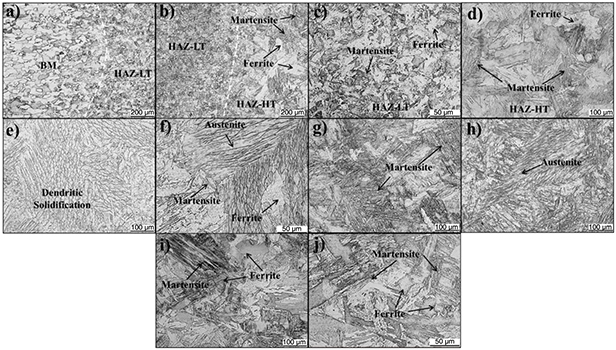 Figure 3. a) Interface between base metal and HAZ-LT, b) interface between HAZ-LT and HAZ-HT, c) HAZ-LT at higher magnification, d)
HAZ-HT at higher magnification, e) and f) weld metal, g) butt joint, welded with filler metal (SS-B1), h) weld metal without
filler metal (SS-B2), i) and j) edge joint, welded with filler metal (SS-E). Figure 3. a) Interface between base metal and HAZ-LT, b) interface between HAZ-LT and HAZ-HT, c) HAZ-LT at higher magnification, d)
HAZ-HT at higher magnification, e) and f) weld metal, g) butt joint, welded with filler metal (SS-B1), h) weld metal without
filler metal (SS-B2), i) and j) edge joint, welded with filler metal (SS-E).
|
|
The Creq and Nieq values were used to estimate the ferrite content for different percent of dilution reported in Table 2. The center of the weld metal (Fig. 3e), corresponds to % Dilution = 47.91 (edge joint with filler metal), which presents a traditional dendritic solidification obtained after a fusion welding
process. These grains follow an epitaxial growth during the solidification, from grains of the base metal toward the fusion
line. The faster cooling rate provides a rapid heat dissipation which can generate equiaxed microstructures in the weld metal.
Amuda and Mridha (2013) found that the equiaxed grain structure is related to the faster cooling rates at the grain coarsening temperature (Villaret
et al., 2013). Higher magnifications of the weld metal (Fig. 3f) reveal the presence of ferrite, austenite and martensite laths. Additionally, the microstructure shown in Fig. 3g indicates that the weld metal produced with a dilution percent of 58.91% (butt joint with filler metal, SS-B1) contains
a higher amount of martensite than the edge joint with filler metal (SS-E) welding condition (Fig. 3h). Figure 3i shows the microstructure characteristics for the welds without filler metal (SS-B2). The presence of martensite laths can
be observed in Fig. 3j. Additionally, the presence of this phase can be deduced if the Creq and Nieq are plotted on a Schaeffler diagram.
3.3. Weld thermal cyclesTOP
To correlate the microstructural transformation in the HAZ (hardness increment), temperature measurements in weld metal, HAZ
and BM were obtained. Figure 4a shows the weld thermal cycles, the maximum temperature reached (1778.2 °C) corresponds to the fusion zone (weld metal) located
at two millimeters from the center of the welding bead. Subsequently, the peak temperatures at 3 mm (HAZ-HT), 6 mm (HAZ-LT)
and 12 mm (BM) were 1258 °C, 1022.1 °C and 539 °C, respectively. Figure 4b, shows that the peak temperatures have been reached in a relatively short time, especially for the thermal cycle located
at the weld metal. The heat transfer in the melting zone to adjacent regions represents the higher temperature gradient which
tends to produce a faster cooling rate, as shown in Fig. 4b.
|
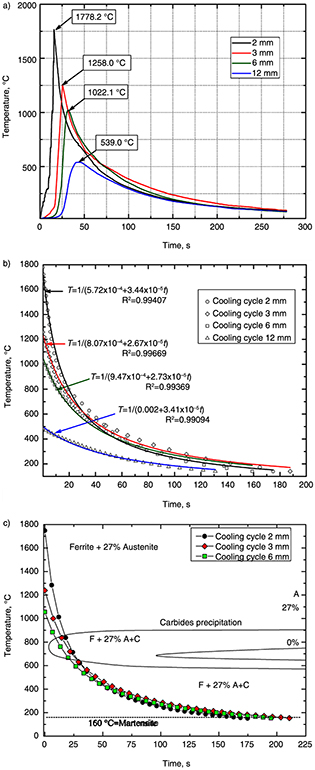 Figure 4. a) Weld thermal cycles, b) cooling section of the weld thermal cycles and c) cooling cycle correlation with the time-temperature-transformation
(TTT) diagram. Figure 4. a) Weld thermal cycles, b) cooling section of the weld thermal cycles and c) cooling cycle correlation with the time-temperature-transformation
(TTT) diagram.
|
|
The weld thermal cycles for the positions at 2, 3 and 6 mm from the center of the welding bead reach the austenization temperature.
The microstructural changes are strongly influenced by these temperatures promoting the precipitation of chromium carbides
and the presence of martensite, which is observed on the TTT diagram in Fig. 4c (Santos et al., 2012). The relatively high cooling rates observed during the welding process prevents the transformation from austenite to ferrite.
According to the TTT diagram, the weld thermal cycle crosses the region of ferrite plus austenite (δ+γ), allowing the transformation
of austenite into martensite at relatively high cooling rates. This aspect tends to increase the local mechanical properties
of the welded joints as discussed below in terms of hardness and tensile strength.
3.4. Tensile and indentationTOP
Tensile results for base metal and welded joints (SS-B1 and SS-B2) are given in Table 3. From conventional stress-strain curves (Fig. 5a) a very well defined elastic behavior was observed, which allows to determine the elastic modulus (198.6 GPa) by a linear
fitting. As can be observed in Table 3, the yield strength for the welded joints tends to be similar than that of the base metal (416 MPa). In contrast, a slight
increasing in tensile strength for the welded joints has been observed. However, the elongation tends to increase in more
than 28% with respect to base metal, which provided an important increment in terms of toughness (fracture energy). The fractures
of the tensile samples were located on the base metal region irrespective of the welding conditions. Therefore, these results
indicate that the weld metal and HAZ are stronger than base metal. This is not surprising because the hardness values on the
different zones indicate a similar behavior. It is to say that local tensile properties tend to increase in comparison with
base metal, which is obtained from the microstructure features, i.e. austenite, ferrite, martensite laths and grain refinement.
Thus, it is likely that the strain hardening capacity tends to increase. Consequently, by increasing the tensile load, the
strain hardening effect becomes saturated, which facilitates the transmission of the load to the adjacent base metal. It is
to say, that a structural effect due to different local mechanical properties of the welded joints exist.
|
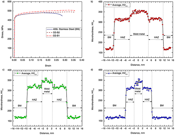 Figure 5. a) Conventional stress-strain curves, and microhardness profiles for: b) edge joint, welded with filler metal (SS-E), c) butt
joint, welded with filler metal (SS-B1) and d) butt joint, welded without filler metal (SS-B2). Figure 5. a) Conventional stress-strain curves, and microhardness profiles for: b) edge joint, welded with filler metal (SS-E), c) butt
joint, welded with filler metal (SS-B1) and d) butt joint, welded without filler metal (SS-B2).
|
|
Table 3. Mechanical properties for base metal and welded joints
| Tensile test results for base metal and welded joints |
| FSS |
Yield strength (MPa) |
Tensile strength (MPa) |
Elongation (%) |
Fracture location |
Toughness (MJ m−3)
|
| 409L stainless steel (BM) |
416 |
480 |
28 |
– |
133.0 |
| SS-B2 |
419 |
490 |
36 |
BM |
170.8 |
| SS-B1 |
422 |
508 |
36 |
BM |
176.6 |
| Hardness and elastic modulus obtained by instrumented indentation |
| Zone |
Hardness HV0.005 |
Elastic modulus (GPa) |
| WM |
380.5 |
203.3 |
| HAZ-HT |
403.0 |
185.8 |
| HAZ-LT |
360.5 |
193.2 |
| BM |
208.3 |
137.7 |
To evaluate the thermal effect produced by the welding process, microhardness measurements were performed according to the
experimental procedure. Three zones with different hardness values were identified as can be observed in Fig. 5 (b-d). The microhardness remains uniformly for the base metal, having values between 170 and 175 HV0.5 in all cases. In contrast for the joints where a filler metal has been used (Fig. 5 b and c), it was observed that the hardness of the weld metal (~350 HV0.5) is higher than the HAZ and base metal for all welded joints. This hardness improvement was attributed to the austenitic
filler metal which has a higher content of Cr and Ni (solid solution hardening) than the base metal, and the presence of martensite
(Fig. 3).
The welded joint without filler metal (SS-B2), shows dispersion in the weld metal microhardness values, this is due to the
heterogeneities in the microstructure of the welding bead (Fig. 5d). The hardness increment in this area was attributed to the presence of martensite laths and ferrite phases. This aspect
has been previously observed by Balmforth and Lippold (1998), who explained that the combination of these phases can have an important variation depending on the amount of ferrite and
martensite.
In the case of the HAZ, the hardness values increased in more than two times with respect to base metal for all welded joints.
However, the HAZ area tends to decrease as function of the heat input. This aspect is very evident for the SS-B2 joint (no
filler metal), where the heat input (586 J mm−1) was approximately 30% less than for SS-E joint (820 J mm−1), and obviously an important decreasing in terms of the HAZ area was observed (Table 2). To appreciate the variations in terms of hardness in the welding profiles a mapping representation of the microhardness
was obtained (Fig. 6).
|
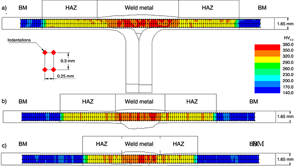 Figure 6. Microhardness maps for: a) SS-E, b) SS-B1 and c) SS-B2. Figure 6. Microhardness maps for: a) SS-E, b) SS-B1 and c) SS-B2.
|
|
The hardness behavior observed in the maps and profiles was a result of different microstructures in the welded joints. Thus,
in order to confirm the presence of ferrite, austenite and martensite, microhardness measurements were performed at 0.01 kg
(98.1 mN) of indentation load. These measurements allow the identification of each phase, i.e. austenite of the weld metal
(Fig. 7 a-b), martensite and coarse ferrite of the HAZ-HT (Fig. 7 c-d) and martensite of the HAZ-LT (Fig. 7 e-f).
|
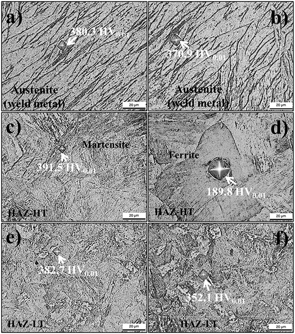 Figure 7. Microhardness values: a-b) austenite in weld metal, c) martensite in HAZ-HT, d) coarse ferrite in HAZ-HT and e-f) martensite
in HAZ-LT. Figure 7. Microhardness values: a-b) austenite in weld metal, c) martensite in HAZ-HT, d) coarse ferrite in HAZ-HT and e-f) martensite
in HAZ-LT.
|
|
On the other hand, to approximate the local hardness and elastic modulus of the welded joints, instrumented indentation tests
were performed in the weld metal, HAZ and base metal of the SS-E weld. The load as function of indenter penetration was employed
to determine the elastic modulus for different zones of the welded joint (Table 3).
From Table 3, it is possible to observe that the elastic modulus of the base metal is below than that reported for a tension test in ferritic
stainless steels (190–200 GPa). Some studies stablished that the elastic modulus obtained by the instrumented indentation
corresponds to a bulk modulus (Ambriz et al., 2011; Dowling, 2013). An additional explanation of this aspect is that in the case of indentation, the elastic and plastic strain is triaxial
and it involves only few grains, while in tension the strain taken for the elastic modulus calculation is uniaxial. For instance,
Pham et al. (2014) reported that the elastic modulus in welds of a structural steel is polymodal with an interval from 130 to 380 GPa. Then,
taking into account the results obtained for the 409L ferritic stainless steel welds, the authors consider to carry out an
exhaustive study in terms of nanoindentation considering dislocation theory to clarify the influence of different metallurgical
conditions of the welded joints.
4. CONCLUSIONSTOP
| – |
The heat input employed in gas tungsten arc welding process induces significance changes in the microstructure of a 409L stainless
steel. The microstructure of the welded joints consists of austenite and some amount of ferrite along with lath martensite. |
| – |
Considering the percent of dilution in the fusion zone, the presence of ferrite and martensite in the weld metal can be achieved. |
| – |
The heat affected zone shows ferrite coarse grains, grain refinement and martensite laths. The martensite is derived from the metastable austenite due to the fast cooling rate during the weld thermal cycle. |
| – |
Independently of the heat input employed for welding, the microhardness values in the heat affected zone (~300 HV0.5), and weld metal (~350 HV0.5) increased with respect to base metal (~172 HV0.5). However, tensile properties of the welded joints increase slightly in comparison with the base metal. In contrast, an elongation increment was obtained, which provide a toughness improvement close to 28% with respect to the base metal. |
ACKNOWLEDGEMENTSTOP
J.A. Delgado thanks CONACyT-México for the scholarship provided. CONACyT and SIP-IPN are also acknowledged by the founds given
to conduct this research.
REFERENCESTOP
| ○ |
Ambriz, R.R., Chicot, D., Benseddiq, N., Mesmacque, G., de la Torre, S.D. (2011). Local mechanical properties of the 6061-T6
aluminium weld using micro-traction and instrumented indentation. Eur. J. Mech. - A/Solids. 30, 307–315. http://dx.doi.org/10.1016/j.euromechsol.2010.12.007.
|
| ○ |
Amuda, M.O.H., Mridha, S. (2013). Grain refinement and hardness distribution in cryogenically cooled ferritic stainless steel
welds. Mater. Design. 47, 365–371. http://dx.doi.org/10.1016/j.matdes.2012.12.008.
|
| ○ |
ASTM E8 (2004). Standard test methods for tension testing of metallic materials. |
| ○ |
Balmforth, M.C., Lippold, J.C. (1998). A preliminary ferritic-martensitic stainless steel constitution diagram. Weld. Res. Supplement. 77, 1s-7s.
|
| ○ |
Bayraktar, E., Moiron, J., Kaplan, D. (2006). Effect of welding conditions on the formability characteristics of thin sheet
steels: Mechanical and metallurgical effects. J. Mater. Process. Tech. 175, 20–26. http://dx.doi.org/10.1016/j.jmatprotec.2005.04.007.
|
| ○ |
Bayraktar, E., Katundi, D., Yilbas, B.S., Claeys, J. (2011). Toughness of welded stainless steels sheets for automotive industry.
J. Achiev. Mater. Manuf. Eng. 44, 35–41.
|
| ○ |
Dowling, N.E. (2013). Mechanical behavior of materials, Engineering Methods for Deformation, Fracture and Fatigue, 4th Ed., Prentice Hall, Upper Saddle River, New Jersey.
|
| ○ |
Hakeem, A.M.O., Shahjahan, M. (2009). Microstructural features of AISI 430 Ferritic Stainless Steel (FSS) weld produced under
varying process parameter. Int. J. Mech. Mat. Eng. 4, 160–166.
|
| ○ |
Katundi, D., Tosun-Bayraktar, A., Bayraktar, E., Toueix, D. (2010). Corrosion behaviour of the welded steel sheets used in
automotive industry. J. Achiev. Mater. Manuf. Eng. 38, 146–153.
|
| ○ |
Lakshminarayanan, A.K., Shanmugam, K., Balasubramanian, V. (2009). Effect of welding processes on tensile, impact, hardness
and microstructure of joints made of AISI 409M FSS base metal and AISI 308L ASS filler metals. Ironmak. Steelmak. 36, 75–80. doi: http://dx.doi.org/10.1179/174328108X378224.
|
| ○ |
Lakshminarayanan, A.K., Balasubramanian, V. (2012). Sensitization resistance of friction stir welded AISI 409 M grade ferritic
stainless steel joints. Int. J. Adv. Manuf. Technol. 59, 961–967. http://dx.doi.org/10.1007/s00170-011-3552-7.
|
| ○ |
Lippold, J.C., Kotecki, D.J. (2005). Welding Metallurgy and Weldability of Stainless Steels. 2nd Ed., Wiley, Hoboken, New Jersey.
|
| ○ |
McGuire, M. (2008). Stainless Steel for Design Engineers. 1st. ASM International, Ohio, USA.
|
| ○ |
Mukherjee, M., Pal, T. (2012). Influence of mode of metal transfer on microstructure and mechanical properties of gas metal
arc-welded modified ferritic stainless steel. Metall. Mater. Trans. A. 43, 1791–1808. http://dx.doi.org/10.1007/s11661-011-1069-1.
|
| ○ |
Niekerk, C.J.V., Toit, M.D. (2011). Sensitization behaviour of 11–12% Cr AISI 409 stainless steel during low heat input welding.
J. S. Afr. I. Min. Metall. 111, 243–256.
|
| ○ |
Okada, O., Nakata, K., Kasahara, S. (1999). Effects of thermal sensitization on radiation-induced segregation in type 304
stainless steel irradiated with He-ions. J. Nucl. Mater. 265, 232–239. http://dx.doi.org/10.1016/S0022-3115(98)00733-8.
|
| ○ |
Pekkarinen, J., Kujanpää, V. (2010). The effects of laser welding parameters on the microstructure of ferritic and duplex
stainless steels welds. Phys. Proc. 5, Part A, 517–523. http://dx.doi.org/10.1016/j.phpro.2010.08.175.
|
| ○ |
Pham, T.-H., Kim, J.J., Kim, S.-E. (2014). Estimation of microstructural compositions in the weld zone of structural steel
using nanoindentation. J. Constr. Steel Res. 99, 121–128. http://dx.doi.org/10.1016/j.jcsr.2014.04.011.
|
| ○ |
Santos, B., Farias, C., Sobral, M. (2012). Spectral analysis of ultrasonic lamb waves applied to the study of the intermetallic
phase presence on plates of AISI 430 ferritic stainless steel submitted to isothermal treatments, 18th World Conference on Nondestructive Testing, pp. 1–10.
|
| ○ |
Sathiya, P., Aravindan, S., Noorul Haq, A. (2007). Effect of friction welding parameters on mechanical and metallurgical properties
of ferritic stainless steel. Int. J. Adv. Manuf. Technol. 31, 1076–1082. http://dx.doi.org/10.1007/s00170-005-0285-5.
|
| ○ |
Shanmugam, K., Lakshminarayanan, A.K., Balasubramanian, V. (2009). Effect of weld metal properties on fatigue crack growth
behaviour of gas tungsten arc welded AISI 409M grade ferritic stainless steel joints. Int. J. Pres. Ves. Pip. 86, 517–524. http://dx.doi.org/10.1016/j.ijpvp.2009.02.002.
|
| ○ |
Villaret, V., Deschaux-Beaume, F., Bordreuil, C., Rouquette, S., Chovet, C. (2013). Influence of filler wire composition on
weld microstructures of a 444 ferritic stainless steel grade. J. Mater. Process. Tech. 213, 1538–1547. http://dx.doi.org/10.1016/j.jmatprotec.2013.03.026.
|