L10 ordered structures in Al-Cu-(Mg) alloys at the early stages of elevated temperature aging
Xia Fuzhong, Wang Mingpu*
Central South University, School of Materials Science and Engineering, 932 Lushan S Rd, Yuelu, 410083 Changsha, China
*Corresponding author: wangmp@csu.edu.cn
| |
ABSTRACT
This study concerns the precipitation structures of Al-3Cu and Al-3Cu-1.78Mg (wt. %) alloys at the early stages of elevated
temperature aging. The Al-3Cu and Al-3Cu-1.78 Mg alloys were solution treated at 540 °C and 500 °C for 2 h, respectively,
and then aged at 190 °C for 2 min. The precipitation structures in aged Al-3Cu-(1.78Mg) alloys were characterized by Transmission
Electron Microscopy (TEM) and High Resolution Transmission Electron Microscopy (HTREM). 001 zone axis Selected area electron
diffraction patterns indicate that L10 ordered structures are formed in the two aged alloys. HRTEM experiments reveal the
partial dislocations on the interfaces of L10 ordered structures. From comparing experimental results with that in the literature,
it is concluded that the L10 ordered structures in aged Al-3Cu alloy consist of Al and Cu atoms, and they are comprised by
Al, Cu and Mg atoms together in the aged Al-3Cu-1.78Mg alloy. On the basis of precipitate growing thermodynamics, it is thought
the L10 ordered structures act as nuclei for GP zones in Al-Cu-(Mg) alloys during aging.
|
| |
RESUMEN
Estructuras ordenadas L10 en aleaciones Al-Cu-(Mg) en los estados iniciales de envejecimiento a temperaturas elevadas. En
este trabajo se estudian las estructuras de precipitación en Al-3Cu y Al-3Cu-1,78Mg (% en peso) en los estados iniciales
de envejecimiento a temperatura elevada. Las aleaciones Al-3Cu y Al-3Cu-1.78 Mg fueron sometidas a un tratamiento térmico
de solución de 2 h a 540 °C y 500 °C, respectivamente, y posteriormente envejecidas 2 min a 190 °C. Las estructuras de precipitación
en Al-3Cu-(1.78Mg) envejecido fueron caracterizadas por microscopía electrónica de transmisión (TEM) y por microscopía electrónica
de transmisión de alta resolución (HTREM). Los diagramas de difracción de electrones de área seleccionada indican que se forman
estructuras ordenadas L10 en las dos aleaciones envejecidas. Experimentos de HRTEM revelan la presencia de dislocaciones parciales
en las intercaras de las estructuras L10 ordenadas. Comparando estos resultados experimentales con la bibliografía, se concluye
que la estructura ordenada L10 en Al-3Cu envejecido consiste de átomos de Al y Cu, y en la aleación Al-3Cu-1.78Mg envejecida
consisten de átomos de Al, Cu y Mg. Sobre la base de la termodinámica del crecimiento de los precipitados, se propone que
la estructura ordenada L10 actúa como de nucleación de las zonas GP en las aleaciones Al-Cu-(Mg) durante el envejecimiento.
|
1. INTRODUCTIONTOP
Precipitation-hardenable Aluminum alloys based on Al-Cu-(Mg) compositions are widely used in structural aerospace applications
due to their excellent mechanical properties. Many researches have been conducted to investigate the precipitation hardening
mechanisms of the alloys. Especially in the past few years, the rapid hardening effect at the early stages of elevated temperature
aging in Al-Cu-Mg alloys has attracted broad attention. For example, Atom Probe Tomography (APT) experiments have demonstrated
the formation of “Cu-Mg” clusters in Al-Cu-Mg alloys at the early stages of artificial aging, which were believed to be responsible
for the initial rapid age hardening of the alloys (Matsubara and Cohen, 1985; Kovarik et al., 2004) have affirmed the formation of L10 Ordered Structures (OS) at the early aging stages in the high Mg content Al-3Mg-0.4Cu-0.12Si
(wt. %) alloy by High Resolution Transmission Electron Microscopy (HRTEM). When it comes to the OS, it is worth noting the
characteristic splitting of the supperlattice spots in associated Selected Area Electron Diffraction (SAED) patterns. Researches
on the L10 OS in an AuCu alloy demonstrated that the strain at the OS interfaces can result in the splitting of supperlattice
spots in SAED patterns into satellite spots (Ogawa et al., 1958; Glossop and Pashley, 1959). However in the work of Kovarik et al. (2004), the splitting of supperlattice spots was not taken into consideration in interpreting the HRTEM and SAED results of the
Al-3Mg-0.4Cu-0.12Si alloy containing L10 OS. In addition, their hypothesis that the L10 OS in the alloy are comprised of Mg
and Cu without Al deserves re-examination, because if the Mg atoms in their proposed model for L10 OS are replaced partially
and randomly by Al atoms, their HRTEM and SAED results can still be explained. In the literature, whether or not OS are formed
in both Al-Cu and low Mg content Al-Cu-Mg alloys at the early stages of artificial aging has not yet been determined. Also
there has been little research on the role of OS in the precipitation processes of Al-Cu-(Mg) alloys. Kovarik et al. (2004) considered L10 OS as GPI zones in the Al-3Mg-0.4Cu-0.12Si alloy. This study aims to address the above issues in Al-3Cu-(1.78Mg) alloys aged at 190 °C for 2 min by TEM and HRTEM experiments.
2. MATERIALS AND METHODSTOP
Al-3Cu-(1.78Mg) (wt. %) ingots were prepared by melting raw materials in a pit furnace under atmosphere. The raw materials
used for melting were: 99.7% pure Al, 99.9% pure Cu, and 99.9% pure Mg. After melting, Al-Cu ingots are homogenized at 530 °C, and Al-Cu-Mg ingots at 490 °C for 24 h. After homogenization the two alloys were hot rolled by 80% at 470 °C, then
Al-Cu plates were solution treated at 540 °C, and Al-Cu-Mg plates at 500 °C for 1 h and quenched into water. After quenching
the two alloys were aged at 190 °C in a salt bath for 2 min. After aging TEM and HRTEM specimens were prepared by cutting
a small piece from the aged samples, mechanically grinding to 60–80 μm thickness and then jet polishing in a solution of 30
vol. % HNO3 and 70 vol.% CH3OH at −20 °C. TEM and HRTEM examination were performed using a JEM 2100 at 200 kV. TEM and HRTEM
image processing were carried out using Gatan Digital Micro software and simulation of SAED patterns by Crystal Maker software.
3. RESULTS AND DISCUSSIONTOP
TEM images and corresponding 001 zone axis SAED patterns (insets of Fig. 1 a-b) of aged Al-3Cu and Al-3Cu-1.78Mg alloys are shown in Fig. 1 (a-b), respectively. It can be seen a small number of lath-like particles (indicated by arrows) precipitate in both two aged
alloys. It should be noted that in our experiments regions as circled in Fig. 1 (a-b) which are free of visible particles were specially selected for SAED examinations. In addition to the lath-like particles,
there seem to be smaller particles precipitated in the matrix of the two alloys as judged from the uneven contrast of the
TEM bright field imagines in Fig. 1. In the SAED patterns of the circled regions in Fig. 1 (a-b) weak spots (labeled with letters) also suggest the presence of some precipitating structures in the matrix. But higher
magnification TEM bright field and HRTEM observations have not revealed any precipitate within the circled areas selected
for SAED experiments in Fig. 1 (a-b), which will be illustrated in the following. As will be demonstrated in latter analysis, the particle-like contrast
of the circled areas in Fig. 1 (a-b) are caused by L10 OS, because chemical micro-inhomogeneity exists between ordered and disordered regions, which gives
rise to the mass thickness contrast which looks like smaller precipitates. In addition, almost the same SAED patterns are
obtained in Fig. 1 (a-b) for the two alloys, except that the diffraction intensities of these labeled weak spots are higher in the Al-Cu-Mg
alloy. Among these weak spots, the {110} supperlattice spots labeled D in Fig. 1 (a-b) are thought by Kovarik et al. (2004) to be caused by L10 OS, which consist of Mg and Cu atoms in their Al-Mg-Si-Cu alloy. The presence of {110} supperlattice
spots in Fig. 1a suggests that L10 OS are also formed in the aged Al-Cu alloy. The model we propose for L10 OS in Al-Cu alloy is shown in
Fig. 2a, in which Al and Cu atoms occupy adjacent {002}Al planes. This model is consistent with Hardy’s investigation (Hardy, 1951) on the aging of Al-Cu alloys which demonstrated that during aging Cu atoms initially precipitate on {002}Al planes. The
simulated 001 zone axis SAED pattern of the Al-Cu alloy containing L10 OS is shown in Fig. 2b. Among these labeled spots in this pattern, the {110} supperlattice spot D comes from the OS variants with {002}Cu planes
perpendicular to the electron beam, spots E and G come from the OS variants with {002}Cu planes parallel to the (0-20) plane,
and G and H come from the OS variants with {002}Cu planes parallel to the (002) plane. By comparing this simulated SAED pattern
with that in Fig. 1 (a-b), we can find only the {110} supperlattice spots are present in experimental SAED patterns, other supperlattice spots
labeled E, F, G and H in Fig. 2b are absent in Fig. 1. Instead, some satellite spots labeled E1, F1, G1 and H1 etc. (hereinafter denominated satellite spots) around the supperlattice
locations E, F, G and H are caused in the SAED patterns of Fig. 1 (a-b), which is schematically illustrated in Fig. 2c.
|
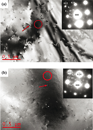 Figure 1. TEM imagines and corresponding 001 zone axis SAED patterns of Al-3%Cu: (a) Al-3%Cu-1.78%Mg; and (b) alloys aged at 190 °C
for 2 min. Note that the SAED patterns come from the circled areas which are free of the lath-like particles arrowed in (a)
and (b). Weak spots in the SAED patterns are labeled following the marking way in Fig. 2c. Figure 1. TEM imagines and corresponding 001 zone axis SAED patterns of Al-3%Cu: (a) Al-3%Cu-1.78%Mg; and (b) alloys aged at 190 °C
for 2 min. Note that the SAED patterns come from the circled areas which are free of the lath-like particles arrowed in (a)
and (b). Weak spots in the SAED patterns are labeled following the marking way in Fig. 2c.
|
|
|
 Figure 2. (a) The model for the L10 ordered structures in Al-Cu alloy; (b) simulated 001 zone axis SAED pattern of Al-Cu alloy as three
types of L10 OS variants in it are considered, in which the {110} supperlattice spot D comes from the OS variants with {002}Cu
planes perpendicular to the electron beam, and the supperlattice spots E, F, G and H are caused by the OS variants with {002}
Cu planes parallel to the electron beam; and (c) simulated 001 zone axis SAED pattern of Al-Cu alloy as the splitting of supperlattice
diffractions by strained L10 OS interfaces is taken into account (see text for further explanation). Figure 2. (a) The model for the L10 ordered structures in Al-Cu alloy; (b) simulated 001 zone axis SAED pattern of Al-Cu alloy as three
types of L10 OS variants in it are considered, in which the {110} supperlattice spot D comes from the OS variants with {002}Cu
planes perpendicular to the electron beam, and the supperlattice spots E, F, G and H are caused by the OS variants with {002}
Cu planes parallel to the electron beam; and (c) simulated 001 zone axis SAED pattern of Al-Cu alloy as the splitting of supperlattice
diffractions by strained L10 OS interfaces is taken into account (see text for further explanation).
|
|
In the following we will explore the origin of the satellite spots in the SAED patterns of Fig. 1 (a-b).
First it can be excluded that these satellite spots come from the lath-like particles arrowed in Fig. 1 (a-b), because regions as circled in Fig. 1 (a-b) which are free of any observable particles were specially selected for SAED examinations. In order to confirm this
argument, both regions with and without lath-like particles in the two alloys are examined by HRTEM. Figure 3 shows the HRTEM and corresponding Fast Fourier Transform (FFT) results of aged Al-3Cu (Fig. 3 a-c) and Al-3Cu-1.78Mg (Fig. 3 d-f) alloys. Among these images, (Fig. 3 b and e) show the FFT results of similar lath-like particles as arrowed in Fig. 1 (a-b), respectively, and Fig. 3 (c and f) show the FFT results of similar regions as circled in Fig. 1 (a-b), respectively. Comparing Fig. 3b with Fig. 3c indicates the structure of the arrowed particle in Al-Cu alloy is the same as that of circled alloy matrix. This structure
should be the L10 OS judged from the {110} supperlattice spots in Fig. 3 (b-c). For the Al-Cu-Mg alloy, the FFT pattern in Fig. 3e indicates the lath-like particle arrowed in Fig. 1b is S phase (Wang and Starink, 2005). In addition, the SAED pattern in Fig. 1b does not correspond to the simulated SAED pattern of S phase proposed by Wang and Starink (2005), meaning that these satellite spots in the SAED pattern of Fig. 1b have no relation to the lath-like particles which can be observed in the TEM bright field image. In the literature, the diffraction
spots locating at the same positions as these satellite spots in Fig. 1b are regarded by some authors from S’’ phase in Al-Cu-Mg alloys (Kovarik et al., 2004; Wang and Starink, 2004). However the presence of the same satellite spot distribution both in Fig. 1 (a-b) leads us to conclude that, in the present experiment, these satellite spots in Fig. 1 (a-b) come from the same precipitation products in Al-Cu and Al-Cu-Mg alloys, and that should be the precipitation of Cu
at the early aging stages of the two alloys. In Fig. 3c and 3f {110} supperlattice spots are evident. In experiments, we have found this always the case, suggesting that L10 OS exist almost
everywhere in the matrix of the two aged alloys. However, other supperlattice spots which should also be caused by L10 OS,
such as the supperlattice spots E, F, G and H schematically shown in Fig. 2b, cannot be found in Fig. 3 (c and f), we will give our explanation to this puzzle in the following.
|
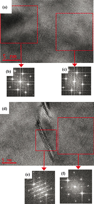 Figure 3. HRTEM micrographs and related fast Fourier transformation (FFT) images of Al-3Cu (a, b, c) and Al-3Cu-1.78Mg (d, e, f) alloys
aged at 190 °C for 2 min. The FFT images in (b) and (e) come from the arrowed particles in Fig. 1 (a-b), respectively, and
FFT images in (c) and (f) from the circled areas in Fig. 1 (a-b), respectively. In b, c and f, except the fundamental diffractions,
only {110} supperlattice spots can be seen. Figure 3. HRTEM micrographs and related fast Fourier transformation (FFT) images of Al-3Cu (a, b, c) and Al-3Cu-1.78Mg (d, e, f) alloys
aged at 190 °C for 2 min. The FFT images in (b) and (e) come from the arrowed particles in Fig. 1 (a-b), respectively, and
FFT images in (c) and (f) from the circled areas in Fig. 1 (a-b), respectively. In b, c and f, except the fundamental diffractions,
only {110} supperlattice spots can be seen.
|
|
In the literature sometimes the same SAED patterns as shown in Fig. 1 (a-b) are attributed to the Al2O3 formed during TEM sample preparation (Phillips, 1975; Park and Ardell, 1983). But if this was the case, the same pattern should also present in the FFT graphs in Fig. 3 (c and f). In addition, we have found in the experiments if the Al-Cu-Mg alloy is overaged, the satellite spots in the SAED
pattern will disappear, suggesting that these satellite spots in Fig. 1b come from specific precipitation products formed at the early aging stages. In view of the above arguments, we think these
labeled weak spots in the SAED patterns of Fig. 1 (a-b) are caused by aging products other than oxides, which will be interpreted in the following.
It can also be excluded that the satellite spots in Fig. 1a and 1b come from the GP zones in the two alloys. GP zones in Al-Cu-(Mg) alloys often take a lath-like morphology (Phillips, 1975; Ajika et al., 1985; Konno et al., 2001), but in this work we selected areas free of any obvious particle for SAED observations. In addition, it has been shown that
in the 001 zone axis SAED patterns of aged Al-Cu-(Mg) alloys, GP zones give rise to intensity streaks passing through the
fundamental spots in the <001> direction (Gerold, 1988; Wang and Starink, 2005). But in the SAED patterns of Fig. 1 (a-b) no streak sign indicating the presence of GP zones can be found.
The presence of satellite spots in the SAED patterns of aged Al-Cu-(Mg) can be interpreted taking into account the splitting
of supperlattice diffractions from OS. As mentioned in the introduction, splitting of supperlattice diffractions often occurs
when the first order supperlattice diffraction beams are diffracted again by strained interfaces of OS. In Al-Cu-(Mg) alloy
it has been shown that interfacial strains perpendicular to the {002}Cu planes exist at the precipitate interfaces as Cu atoms
precipitate on {002}Al planes during aging (Ajika et al., 1985). Under conditions without the splitting of supperlattice diffractions, the L10 OS variants with {002}Cu planes parallel
to electron beam should cause supperlattice spots E, F, G and H (illustrated in Fig. 2b) at {100} positions in the 001 zone axis SAED pattern. However, under this condition, the strained interfaces of the OS variants
are nearly parallel to the {100} supperlattice diffractions, which will induces the secondary diffraction of expected {100}
supperlattice diffractions, making the expected {100} supperlattice spots split in SAED patterns along {200} directions which
are perpendicular to the strained interfaces of OS. So satellite spots around the {100} supperlattice diffractions as schematically
shown in Fig. 2c are present in the experimental SAED patterns of Fig. 1 (a-b). For the L10 OS variants with {002}Cu planes perpendicular to incident electron beam under the 001 zone axis, strained
interfaces of the OS variants are nearly perpendicular to the {110} supperlattice diffractions also, which keeps the {110}
supperlattice diffractions from being diffracted by the strained OS interfaces, so the {110} ordered diffractions caused by
this type of OS variants are present in Fig. 1 (a-b) without being split.
Because the satellite spots are caused by interfacial diffraction, a large area containing enough strained interfaces needs
to be selected to result in visible diffraction intensities in SAED patterns and FFT images of HRTEM graphs. But in Fig. 3 (c and f) diffraction spots come from an area which is much smaller than that selected for SAED examinations in Fig. 1 (a-b), so the satellites spots visible in Fig. 1 (a-b) are covered by background noise in Fig. 3 (c and f), although under bright-field TEM observations, the areas selected for FFT in Fig. 3 (c and f) look the same as that selected for SAED observations in Fig. 1 (a-b).
By choosing all the {110} supperlattice spots in Fig. 3f to perform inverse fast Fourier transformation (IFFT), the {110} plane projection image of Fig. 3f is obtained as shown in Fig. 4. In this figure, the local areas with clear lattice fringes are where the L10 OS locates. Except the L10 OS, some edge dislocations
with one extra {220} half-plane are also illustrated in Fig. 4. Because a perfect edge dislocation in fcc crystals contains two extra {220} half-planes (Pan et al., 1998), the edge dislocations illustrated in Fig. 4 are not the perfect edge dislocations. It has been shown in the literature partial dislocations often exist at the OS interfaces
(Glossop and Pashley, 1959).
|
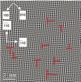 Figure 4. {110} plane projection image of Fig. 3f obtained by choosing all the {110} supperlattice spots in Fig. 3f to perform inverse
fast Fourier transformation. Related projected directions of crystalline planes and some partial dislocations with one extra
{220} half-plane and are illustrated. Figure 4. {110} plane projection image of Fig. 3f obtained by choosing all the {110} supperlattice spots in Fig. 3f to perform inverse
fast Fourier transformation. Related projected directions of crystalline planes and some partial dislocations with one extra
{220} half-plane and are illustrated.
|
|
The L10 OS in Al-3Mg-0.4Cu-0.12Si alloy were considered by Kovarik et al. (2004) to be comprised of Mg and Cu atoms without Al (Kovarik et al., 2004). However, APT experiments have indicated that Cu-Mg clusters formed in Al-Cu-Mg alloys at the early stages of artificial
aging contain considerable Al atoms (Marceau et al., 2010). Between the SAED patterns in Fig. 1 (a-b), except the higher diffraction intensities from L10 OS in the Al-Cu-Mg alloy, no other differences can be identified.
This means that in Al-Cu-Mg alloy Mg can promote the formation of L10 OS during aging without changing the precipitation structure
shown in Fig. 2a. So we conclude that the L10 OS in Al-Cu-Mg alloy are comprised of Al, Cu and Mg atoms, with Mg randomly replacing some Al
atoms in the model shown in Fig. 2a. The higher Mg content in the alloy is the more Al atoms in OS will be replaced by Mg.
At last we shall make some comments on the relationship between the L10 OS and GP zones in Al-Cu-(Mg) alloys. As has already
been discussed earlier, the L10 OS are not GP zones. They have no clear morphologies in both bright-field TEM and HRTEM images
as shown in Fig. 1 and Fig. 3, respectively. We think the L10 OS can be regarded as nuclei for GP zones. This proposition means that the precipitation
processes in Al-Cu-(Mg) alloys begin with gradual enrichment of Cu atoms on {002}Al planes, generating the L10 OS at the same
time. At the early stage of their growth, the L10 OS grow up in all directions to an irregular or globular shape by increasing
and enlarging the {002}Cu plane layers within them, and interfacial strains perpendicular to the {002}Cu planes at the OS
interfaces increase gradually with their growth. As the OS grows to a critical size, the interfacial strains are so large
that lath-like shape will be the most favorable morphology for L10 OS to take in order to decrease the elastic interfacial
strain and grow continually. This means that not all {002}Cu planes already formed in OS can keep growing out along the {002}Al
planes. That most likely to occur is only one layer of {002}Cu plane can keep growing out, bringing about GPI zones. Next
with more Cu atoms diffusing from surrounding matrix into the GPI zones, another {002}Cu plane can grow out also, bringing
about GPII zones. So we propose the decomposition processes of Al-Cu-(Mg) alloys during artificial aging as follows: solid
solution→L10 OS→GPI zones →GPII zones→θ’(S’)→θ(S). The multi-layer GPI zones reported by some authors in the literature may
be the L10 OS which have not yet grown to the critical size to evolve into GPI zones (Matsubara and Cohen, 1985; Höno et al., 1986).
4. CONCLUSIONSTOP
The formation of L10 OS is the mutual precipitation processes occurring at the early stages of elevated temperature aging
in Al-Cu and Al-Cu-Mg alloys. 001 zone axis SAED patterns of the two alloys can be interpreted by taking into account the
existence of L10 OS and electron diffraction on strained interfaces of L10 OS. L10 OS in Al-Cu-Mg alloy are comprised of Al,
Cu and Mg atoms together. The decomposition processes of Al-Cu-(Mg) alloys begin with the formation of L10 OS, from which
GPI zones develop in order to minimize interfacial strains.
REFERENCESTOP
| ○ |
Ajika, N., Endoh, H., Hashimoto, H., Tomita, M., Yoshida, H. (1985). Interpretation of atomic-resolution electron microscope
images of Guiner-Preston zones in aluminium-copper alloys. Philos. Mag. A 51 (5), 729–744. http://dx.doi.org/10.1080/01418618508245284.
|
| ○ |
Gerold, V. (1988). On the structures of Guinier-Preston zones in Al-Cu alloys introductory paper. Scripta Metall. 22 (7), 927–932. http://dx.doi.org/10.1016/S0036-9748(88)80077-2.
|
| ○ |
Glossop, A.B., Pashley, D.W. (1959). The direct observation of anti-phase domain boundaries in ordered Copper-Gold (CuAu)
alloy. P. Roy. Soc. A-Mat. Phy. 250 (1260), 132–146. http://dx.doi.org/10.1098/rspa.1959.0056.
|
| ○ |
Höno, K., Satoh, T., Hirano, K. (1986). Evidence of multi-layer GP zones in Al-1.7at.% Cu alloy. Philos. Mag. A 53 (4), 495–504. http://dx.doi.org/10.1080/01418618608242848.
|
| ○ |
Hardy, H.K. (1951). The ageing characteristics of binary Aluminium-Copper Alloys. J. Inst. Met. 79, 321–369.
|
| ○ |
Konno, T.J., Hiraga, K., Kawasaki, M. (2001). Guinier-Preston (GP) zone revisited: atomic level observation by HAADF-TEM technique.
Scripta Mater. 44 (8-9), 2303–2307. http://dx.doi.org/10.1016/S1359-6462(01)00909-5.
|
| ○ |
Kovarik, L., Gouma, P.I., Kisielowski, C., Court, S.A., Mills, M.J. (2004). A HRTEM study of metastable phase formation in
Al–Mg–Cu alloys during artificial aging. Acta Mater. 52 (9), 2509–2520. http://dx.doi.org/10.1016/j.actamat.2004.01.041.
|
| ○ |
Marceau, R.K.W., Sha, G., Ferragut, R., Dupasquier, A., Ringer, S.P. (2010). Solute clustering in Al–Cu–Mg alloys during the
early stages of elevated temperature ageing. Acta Mater. 58 (15), 4923–4939. http://dx.doi.org/10.1016/j.actamat.2010.05.020.
|
| ○ |
Matsubara, E., Cohen, J.B. (1985). The G.P. zones in Al-Cu alloys-II. Acta Metall. 33 (11), 1957–1969. http://dx.doi.org/10.1016/0001-6160(85)90118-X.
|
| ○ |
Ogawa, S., Watanabe, D., Watanabe, H., Komoda, T. (1958). The direct observation of the long period of the ordered alloy CuAu(II)
by means of electron microscope. Acta Crystallogr. 11, 872–875. http://dx.doi.org/10.1107/S0365110X58002462.
|
| ○ |
Pan, J.S., Tong, J.M., Tian, M.B. (1998). Fundamentals of Materials Science, TsingHua University Press, Beijing.
|
| ○ |
Park, J.K., Ardell, A.J. (1983). Microstructures of the commercial 7075 Al alloy in the T651 and T7 tempers. Metall. Trans. A 14 (10), 1957–1965. http://dx.doi.org/10.1007/BF02662363.
|
| ○ |
Phillips, V.A. (1975). High resolution electron microscope observations on precipitation in Al-3.0% Cu alloy. Acta Metall. 23 (6), 751–767. http://dx.doi.org/10.1016/0001-6160(75)90058-9.
|
| ○ |
Wang, S.C., Starink, M.J. (2004). The assessment of GPB2/S′′ structures in Al–Cu–Mg alloys. Mat. Sci. Eng. A-struct 386 (1-2), 156–163. http://dx.doi.org/10.1016/j.msea.2004.07.006.
|
| ○ |
Wang, S.C., Starink, M.J. (2005). Precipitates and intermetallic phases in precipitation hardening Al–Cu–Mg–(Li) based alloys.
Int. Mater. Rev. 50 (4), 193–215. http://dx.doi.org/10.1179/174328005x14357.
|